To-Do List
- code update: to-do list (12/18)
- get ratio figures online (12/18)
- add description to ratio figs (12/18)
- notable progress on 'Results' (12/19)
- finish ModYY description (12/20)
05/18-05/22
Grid Changes
The outer grid should be functioning correctly now. Rather than computing in an inertial frame, I am computing in a non-rotating frame which is centered about the progenitor and which has a center-of-mass translating about $\Omega t$, i.e.,
$$ \vec{R}_{cm} = \frac{R_{sep}M_s}{M_p+M_s}\left(\cos(0, \Omega t), \sin(\Omega t)\right) $$The pseudo-force is negligible here and does not create any artifacts. Below are images of the inner grid (out to 4xRsep) and the outer grid (~4xSEP to 50xSEP) after a single orbit.

Looking along the Polar axis. There are no noticeable artifacts when viewing the full density range.

Looking along the orbital plane. Same density scale as [left], the grid is difficult to identify.

When narrowing the density range, a portion of the inner grid is visible.

From this view, it may be creating a small artifact.
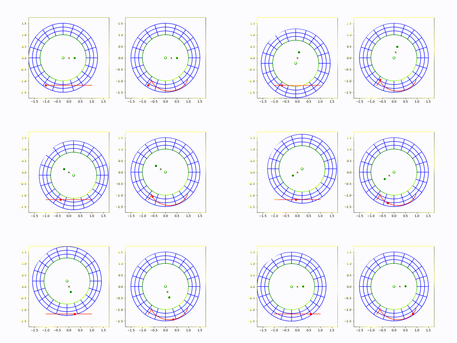
Here is an animation demonstrating the reference frame:

The image on the left is an inertial frame, where the progenitor (small green circle) and secondary (green dot) are both orbiting around CM (black x). The image on the right is the one I'm proposing, where the frame is non-rotating, but is translating so that the progenitor always remains centered.
Slight Issue
When I was testing this in low-resolution, there were no visible artifacts. When moving to high-resolution, setting the minimum radius of the outer grid to the maximum radius of the inner grid is not possible at the resolution I have been using because the first ghost zone is positioned after the [center of the] last radial zone on the inner grid.
I will play around with changing the resolution and/or the outer radius of the outer grid as well as just interpolating this datapoint.


